Let there be sound!

Finally the time has come to power the assembled amp up. What can I say? I´m really delighted by the clean tones. It´s not like later Blackface Fender sounds, but has a kind of wooden quality to it. I guess this comes mostly from the enclosure and the speakers. The overall sound is mostly bright and gets raspy once hit hard.

Image

The guitar I used in the following sound samples is a ´81 Hamer Prototype, which is an all mahogany setneck guitar with a single coil shaped humbucker (OBL) at the neck.

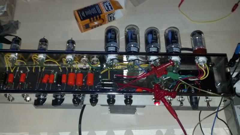
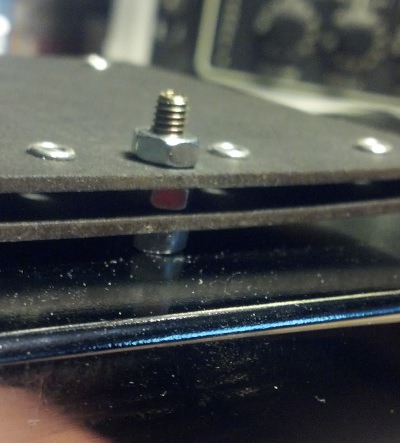
This is a recording from the situation you see in the picture: Guitar straight into the amp, bright channel, no effects, U87Ai a meter away from the amp and also straight through a clean mic pre into the ADC. The sound is beautifully threedimensional and organic.

http://db.tt/7P7ucXs5

Then I added a bit of reverb and quite a bit of delay coming from my old Boss GT-6 to the amps sound.

http://db.tt/zDLLf8Pm

The amp doesn´t stay clean very long. With the pickups in this guitar it begins to distort at around 3-4 on the volume knob´s scale. While a little overdrive creeping in when you hit the strings hard sound kind of charming to me, I´m not sure whether I really like the overdrive sound. The sizzling highs sit somewhere between 8-10kHz and don´t sound good to me. I used the “normal” channel for that and a SM57 microphone to make the following sample bearable:

http://db.tt/FzApw4y1

Here are my settings on the amp:

I´m currently thinking about modifying the amp to stay more clean. 4 6L6CG should be able to be a lot louder without distorting. I have not yet tried to explore it further, but I guess the distortion doesn´t come from the power tubes at all, but one of the preamp or the phase inverter stage.

Any suggestions?

Test, one, two

Now that everything´s in place, the moment of thruth inevitable had come. Power up! Unfortunately the documentation supplied with the kit doesn´t say a single word on testing or at least give some voltage readings. The good news is that there are enough 5F8A schematics to be found that do have some voltage marks.

The very first quality assurance I had already done when I had finished wiring the board to the sockets and pots. I connected a 32V= power supply to the point where the high voltage would go later and checked with a voltmeter that all my wirings and solderpoints were good.

So I was already very confident when I first made the “real” test with the mains attached.

To be sure that I wired the mains transformer correctly, I left off all the tubes except the rectifier tube and measured the high voltage at the Standby switch and the negative voltage near the silicon diode.

Image

Isn´t that a nice vintage voltmeter? 🙂

Next step was to install all the tubes and check some of the voltages I read from the other schematic.

Image

I used the following points for measurement:

Image

My build tested well and all values were within reasonable tolerances!

Power and three more holes

After knitting the board into its housing I grabbed the big iron chunk that acts as the mains transformer and tried to come up with a strategy on how to put this part of the amp together. Especially attaching the power cord was kind of a mystery to me. The two clamps provided as strain relief didn´t fit on any of the transformer studs, as I had supposed when I first had checked the kit.

Image

And besides that I couldn´t find a separate mounting point for the protection earth. So the conclusion for me was to drill three more holes into the chassis. Two for the strain relief clamps for the power cord and one for the protection earth (PE).

Image

Image

I needed to take care of the size of the screws I used for this, because they are covered by the transformer and there is very little space underneath the transformer.

Image

The hole where the power cord escapes the chassis is quite large.

Image

Although there is a nice grommet in place, I pushed a bend protection from an old cinch jack over the cable to be on the safe side.

Image

The wiring diagram suggests to connect the power cord to the “Ground” switch and then wire from there. The Ground switch isn´t really used (the original had a capacitor connected to ground that could be switched to either of the two power leads. This capacitor was obviously omitted from the kit because this doesn´t comply to today´s safety standards anymore). I decided to once again deviate from the suggested wiring and connect directly to the fuse and the Power switch.

I prepared the power cord to have a rather long PE lead so that a breakage in the power leads will let the PE breaks the last as a safety measure.

Image

The PE is connected to its very own contact point and marked as such. Note how tight the strain relief sits in the gap between transformer and chassis. I saw pictures where the strain relief was  attached to the far left wall of the chassis. This would leave a lot of space, but this way the chassis doesn´t fit under my box drill and I didn´t want to drill through this very hard material with a handheld machine. YMMV.

Image

Wiring the mains transformer to the rest was a comparably easy task.

Image

Same can be said about the output transformer and the choke.

Image

Wiring, wiring, wiring…

Now that most mechanical parts are in place and the board is fully assembled, I can begin wiring all together. I had already soldered the one end of the yellow wires to the board so that I just have to cut it appropriately and solder to the pots, jacks and sockets.

Image

This will result in some excess wire to be used, but the kit had 7.5m of the yellow stuff, so no need to restrict oneself. I began the work on the pot/jack side of the chassis. My reasoning was, that once I come to the more delicate tube sockets, I would already have gotten rid of the wires I don´t need to deal with.Image

After that I moved to the tube sockets and began with V1. First I imagined to do the circuit wiring first for all tubes and then install the heater wires (green wires), but figured it would be easier to all at once for each tube. It was easier to go from bottom to top for each socket. I would solder pins 6-9 first (including one heater wire) and then move on with pins 1-5.

The heater wire should be twisted to reduce hum. I found it easier to twist longer portions of the wire and then cut it to length. I guess this is really a matter of taste.

Image

Image

Image

Image

While wiring the power tube sockets I decided to use the black wire for the ground connections. Well, by now I found out that this wire was indeed meant to used for the speakers later. So please don´t do it that way if you don´t have other wire for the speakers! (Fortunately I have other choices).

Image

Image

Minor Schematic Error

I just found out, that the inputs on the schematic are labeled wrong. The amp has two inputs (Bright and Normal) and each input has two jacks (1 and 2). The supplied schematic has the 1 and 2 jacks switched. It makes more sense to have the 1M resistor on input jack and the wiring diagram is also in line with that.

I checked with other schematics I found in the net, like this one.

Installing the Mechanical Parts

Next step I took was to mount all the mechanical parts like sockets, switches and pots. I used the 3130 screws for the large tube sockets (power tubes and rectifier) and the 3120 for the preamp tube sockets.

Image

Then I installed the switches, fuse holder and pilot light. Although the kit contains a bag of lock washers, these don´t fit the switches and their number suggests that they are intended for the pots and plugs only. Fortunately I found a lock washer large enough for the fuse holder and helped myself with Locktite 243 for switches. I think that this is really important: the switches don´t tighten well and are prone to come loose. This is kind of a safety thing in my eyes since these parts are carrying the mains voltage!

No lock washers, use Locktite instead

Image

Before installing the pots I took the opportunity to already solder one leg to the housing where necessary. The supplied lock washers can be used now and I´m happy that I bought a tool for the pot nuts a while ago. This helps preventing more scratches. You can see it on the picture with the filter caps. It´s the T-shaped tool lying on the table.

Image

Image

I figured before installing the main board I need to put the filter caps into place. Otherwise I wouldn´t have a chance to mount it later because the screws are covered then.

Wires, which wires?

The kit comes with 7.5m of yellow wire, 3m of green, and 1m each of red, white and black. The green, white and black are 18awg stranded wire and the others are 22awg solid wire. (BTW “awg” means “American Wire Gauge” and the higher the number, the thinner the wire.) The supplied documentation just says “Wires not specified are CB3035, Yellow 22AWG”. The green one obviously should be used for the tube heaters.But what about red, white, black? All other color labelling in the wiring diagram talks about wires coming from transformers, choke or mains cable. These need to be checked against the documentation of the parts, but I´ll come to that later.

So I have to admit I couldn´t figure where the red, white and black wires should go. While instaling the filter caps I decided to use these to make sure that I don´t mistake any wire and use them for color coding the four wires that go from the top side of the chassis to the bottom. Without colors these would have been very hard to distinguish.

Image

I used the smaller screws (3130, the same as for preamp tubes) to mount the cover for the filter caps. These screws must not stick out more than a few millimeters. Otherwise you get into problems installing the eyelet board.

Image

Image

Received the Fuse

I received a package from Tube Amp Doctor yesterday. Could that be the promised fuse? Yes! The packaging was a bit on the large side though. And funny enough the two little parts found their way out of the bag and were lying in the box separately. But they´re ok!

Once again superbe service and very fast delivery. Plus I begged for an extra fuse and this wish came true as well. Thanks a lot TAD!

Image

Assembling the boards

This is actually the first time I soldered eyelet boards. Kind of funny if you are used to multi layer pcbs and narrow pitched ICs. This is like crochet work. But no mystery about that. It´s easy to do and very forgiving. In fact I enjoyed the use of the old fashioned pushback wire. No cutting off isolation, just pull the fabric back a little, solder the wire, finished.

I guess this was the easy part of the amp. We´ll see how this all stuffs into the chassis.

Ooops, first scratch

I just discovered that the nice shiny chrome face of the chassis has a scratch. Eeek! :-/ I´m sure the thing was 100% perfect when I got it. Maybe I wasn´t careful enough while drilling the holes. The surface is obviously very sensitive. So better cover the the part of the chassis while handling!

Checking Parts

First thing I do with any new build is to spread all the parts on my table ordered by their type. I want to make sure, that I have all I need. With this kit all was very easy. Usually such projects start  with a hunt for parts, but not here. Everything already there and properly labelled. Well, almost everything…

I found out, that the supplied fuse wasn´t the right size. Not a big deal, one email to TAD later I was promised to get the right one soon.

What I could not make out is how the eyelet boards were intended to be fastened to the chassis. The number and size of the supplied screws suggest, that the eyelet board should be directly held by two screws and their respective nuts. Only with another blank isolation board between it and the chassis. I decided to use my own M4 screws for that and use some more nuts as spacers inbetween the boards.

A little more documentation on how the mechnical parts were intended to be used would have been nice. At least a drawing for the placement of the two holes was included.

But beware! You need to drill four more holes! The filter caps needs two and there is a solder terminal that also wants two holes. And this goes into a thick sheet of chrome steel. I´m fortunate to have a good box column drill. But I have an itch that not every DIYer has one. So this could be an issue to some.

I personally had more concerns with the two holes that need to go into the enclosure. It´s easy to drill in the soft wood, but also very easy to misplace these holes and it would be a mess! I managed to get them right, but you need extra care. I have no idea why TAD doesn´t put them in in the first place.