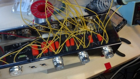
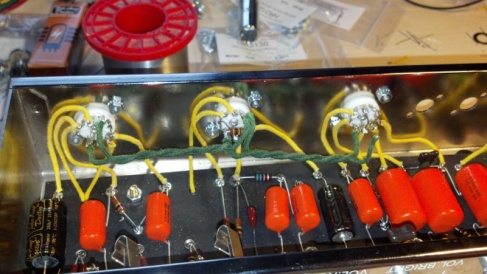
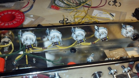
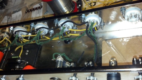
Now that most mechanical parts are in place and the board is fully assembled, I can begin wiring all together. I had already soldered the one end of the yellow wires to the board so that I just have to cut it appropriately and solder to the pots, jacks and sockets.
This will result in some excess wire to be used, but the kit had 7.5m of the yellow stuff, so no need to restrict oneself. I began the work on the pot/jack side of the chassis. My reasoning was, that once I come to the more delicate tube sockets, I would already have gotten rid of the wires I don´t need to deal with.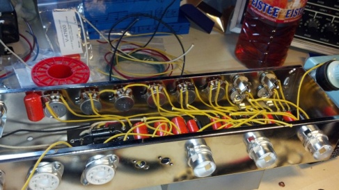
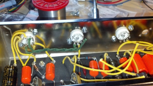
After that I moved to the tube sockets and began with V1. First I imagined to do the circuit wiring first for all tubes and then install the heater wires (green wires), but figured it would be easier to all at once for each tube. It was easier to go from bottom to top for each socket. I would solder pins 6-9 first (including one heater wire) and then move on with pins 1-5.
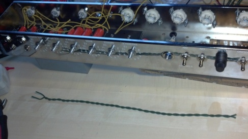
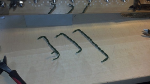
The heater wire should be twisted to reduce hum. I found it easier to twist longer portions of the wire and then cut it to length. I guess this is really a matter of taste.
While wiring the power tube sockets I decided to use the black wire for the ground connections. Well, by now I found out that this wire was indeed meant to used for the speakers later. So please don´t do it that way if you don´t have other wire for the speakers! (Fortunately I have other choices).
